Demystifying PCB Materials: A Comprehensive Guide for Electronics Manufacturers
.
PCB Materials: The Foundation of Modern Electronics
Imagine a tiny orchestra. Every instrument (electronic component) needs to play its part in perfect harmony for the music (electrical signals) to flow flawlessly. But what holds it all together, ensuring each note rings true? The stage upon which this symphony plays out – the PCB material.
Understanding PCB materials goes beyond just choosing the right platform for your electronic components. It’s about ensuring the very foundation of your device functions flawlessly. Delving into this world empowers you to make informed decisions, selecting the perfect material to bring your project to life.
What are PCB Materials?
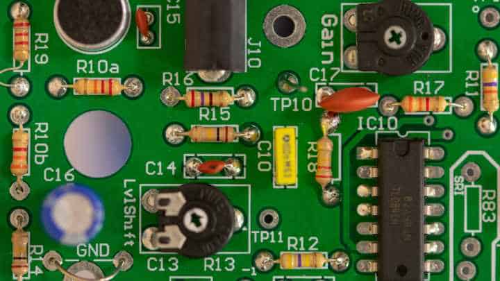
At the heart of every PCB lies a layered structure. The base layer, forming the foundation, is the PCB material. Think of it as the canvas upon which the intricate world of electronics comes to life. But this canvas isn’t a simple sheet of plastic. It’s a carefully chosen material, boasting specific properties that significantly impact the performance and functionality of your entire device.
- Substrate: The core layer, typically a rigid material like fiberglass or ceramic, providing structural support and a platform for mounting electronic components.
- Dielectric Layer: A layer of insulating material separating conductive traces, preventing unwanted electrical shorts and ensuring proper signal transmission.
- Copper Foil: Thin sheets of copper bonded to the substrate, serving as the conductive pathways for electrical signals.
Table 1: Common PCB Substrate Materials
| Material | Description | Advantages | Disadvantages |
|---|---|---|---|
| FR4 (Flame Retardant 4) | The most widely used PCB material, known for its durability, cost-effectiveness, and good electrical properties. | Affordable, readily available, flame retardant. | Lower thermal conductivity compared to some materials. |
| CEM-3 (Composite Epoxy Material) | A cost-competitive alternative to FR4, offering similar electrical properties but with a slightly lower heat resistance. | Budget-friendly, good for low-power applications. | Not ideal for high-performance applications due to lower thermal properties. |
Why Choosing the Right PCB Material Matters
Selecting the right PCB material isn’t just about finding a flat surface to hold your components. It’s akin to choosing the foundation for your house. A weak foundation can lead to cracks and instability, jeopardizing the entire structure. Similarly, an inappropriate PCB material can significantly impact your device’s performance, reliability, and even safety.
Here’s why choosing the right PCB material is crucial:
- Electrical Performance: Different materials exhibit varying electrical properties like dielectric constant and impedance. These factors directly influence signal transmission efficiency and can cause signal distortion or even complete failure if not chosen carefully.
- Thermal Management: Certain electronic components generate heat during operation. The PCB material needs to effectively dissipate this heat to prevent overheating and potential damage to delicate components. Materials with high thermal conductivity are ideal for such applications.
- Mechanical Strength: PCBs experience physical stress during assembly and operation. The chosen material must possess adequate mechanical strength to withstand these stresses and maintain the structural integrity of the board.
- Cost-Effectiveness: PCB materials come in a range of prices. Striking a balance between functionality, performance requirements, and budget is essential.
- Environmental Regulations: Certain regulations, like RoHS (Restriction of Hazardous Substances), restrict the use of specific materials due to environmental concerns. Choosing compliant materials ensures your device meets these regulations.
By understanding these factors and carefully selecting the right PCB material, you lay a solid foundation for a reliable, functional, and safe electronic device.
Exploring Common PCB Substrate Materials
Choosing the right PCB material is akin to selecting the perfect building block for your electronic device. Just as a house needs a sturdy foundation, your PCB requires a substrate material that delivers the necessary properties for optimal performance. Let’s delve into some of the most common PCB substrate materials and explore their strengths and limitations:
FR4 (Flame Retardant 4): The Workhorse Material
FR4 has reigned supreme as the most widely used PCB substrate material, accounting for an estimated 70% of the global PCB market. Earning its reputation for:
- Versatility: FR4 offers a good balance of electrical properties, making it suitable for a wide range of applications. This versatility is evident in its ability to handle signal frequencies up to around 1 GHz.
- Flame Retardancy: As the name suggests, FR4 complies with UL 94V-0 flammability standards. This translates to a self-extinguishing characteristic, a crucial safety feature for electronic devices, especially in applications where fire hazards cannot be tolerated.
- Machinability: The material boasts good machinability, allowing for efficient drilling and routing during PCB fabrication. This translates to faster production times and potentially lower manufacturing costs compared to some other materials.
However, FR4 also has limitations:
- Thermal Conductivity: While adequate for many applications, FR4’s thermal conductivity is lower compared to some other materials. This can be a concern for high-power devices that generate significant heat. FR4’s thermal conductivity is around 0.3 – 0.4 W/mK, which may not be sufficient for applications requiring efficient heat dissipation.
- High-Frequency Performance: FR4 may not be the ideal choice for applications involving extremely high-frequency signals due to potential signal loss at frequencies exceeding around 1 GHz. As signal frequencies rise, the dielectric properties of FR4 can introduce unwanted signal attenuation.
Overall, FR4 remains a reliable and cost-effective workhorse for a vast range of electronic projects, particularly those requiring a balance between functionality and affordability. While other materials may offer superior properties in specific areas like thermal conductivity or high-frequency performance, FR4’s well-rounded characteristics and established manufacturing processes make it a popular choice for countless applications.
Table 2: Typical Properties of FR4
| Property | Value |
|---|---|
| Dielectric Constant | 4.3 – 4.5 |
| Glass Transition Temperature (Tg) | 130°C – 140°C |
| Thermal Conductivity | 0.3 – 0.4 W/mK |
CEM-3 (Composite Epoxy Material): A Cost-Effective Option
CEM-3 stands as a budget-friendly alternative to FR4, offering similar electrical properties at a slightly lower cost. Here’s a closer look at its key attributes:
- Cost-Effectiveness: CEM-3 boasts a lower material cost compared to FR4. This makes it an attractive option for cost-sensitive applications such as low-power consumer electronics. Statistics indicate that CEM-3 can be around 10-20% less expensive than FR4.
- Machinability: Similar to FR4, CEM-3 offers good machinability, enabling efficient drilling and routing during PCB fabrication. This translates to faster production times and potentially lower manufacturing costs.
However, CEM-3 also comes with limitations:
- Lower Heat Resistance: CEM-3 exhibits a slightly lower glass transition temperature (Tg) compared to FR4. This translates to a reduced tolerance for high operating temperatures. While suitable for low-power applications, it may not be ideal for devices generating significant heat.
- Flame Retardancy: While some formulations of CEM-3 offer flame retardant properties, they may not comply with the same stringent standards as FR4. This can be a factor to consider for applications with specific safety regulations.
Table 3: Typical Properties of CEM-3
| Property | Value |
|---|---|
| Dielectric Constant | 4.2 – 4.5 |
| Glass Transition Temperature (Tg) | 100°C – 120°C |
| Thermal Conductivity | 0.2 – 0.3 W/mK |
In essence, CEM-3 offers a cost-effective solution for low-power applications that prioritize affordability and efficient production. However, its lower heat resistance and potential limitations in flame retardancy necessitate careful consideration for applications with specific thermal or safety requirements.
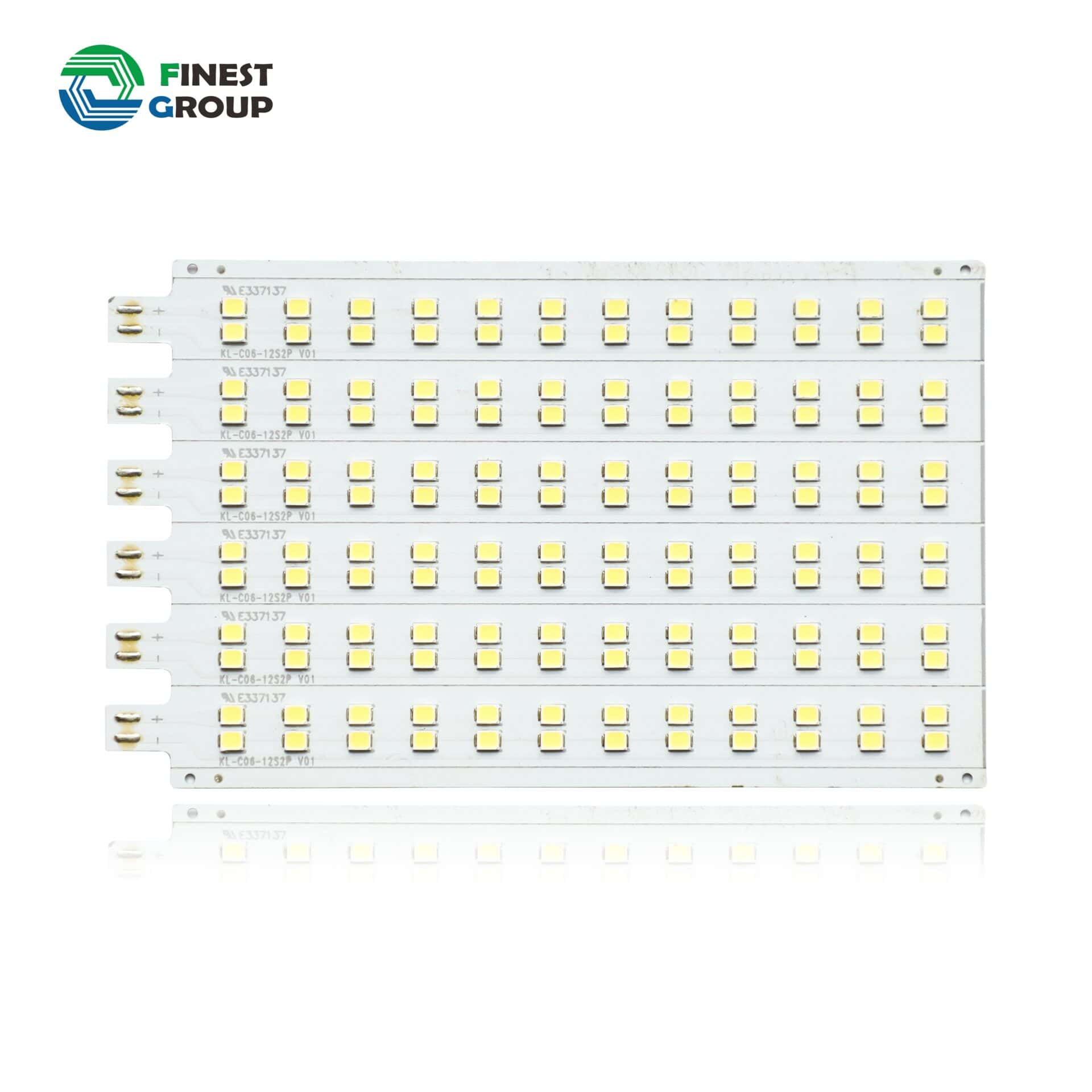
Metal Core PCBs: For High-Performance Applications
When the need arises for superior thermal management and high-frequency signal transmission, metal core PCBs come into play. These PCBs incorporate metal layers within the substrate, offering distinct advantages:
- Exceptional Thermal Conductivity: The presence of metal significantly enhances the PCB’s ability to dissipate heat. This makes them ideal for high-power electronic devices like power converters and LED drivers, where efficient heat management is crucial for performance and reliability. Studies have shown that metal core PCBs can achieve thermal conductivities exceeding 100 W/mK, compared to FR4’s 0.3 – 0.4 W/mK.
- Improved Electrical Performance: The metal core construction minimizes signal loss at high frequencies. This makes metal core PCBs suitable for applications involving high-speed data transmission, such as radiofrequency (RF) devices and high-performance computing systems.
However, metal core PCBs also have drawbacks:
- Higher Cost: The incorporation of metal layers increases the material cost and complexity of fabrication, making them more expensive than FR4 or CEM-3.
- Weight: The presence of metal adds to the overall weight of the PCB. This can be a consideration for applications where weight minimization is a priority, such as in portable devices or aerospace electronics.
Table 4: Typical Properties of Metal Core PCBs
| Property | Value |
|---|---|
| Dielectric Constant | Varies depending on the specific material combination |
| Thermal Conductivity | > 100 W/mK |
| Weight | Higher compared to FR4 or CEM-3 |
Applications: Metal core PCBs find application in various demanding environments:
- Telecommunications equipment: Due to their ability to handle high-frequency signals effectively.
- Power electronics: For their superior thermal management capabilities.
- Medical devices: Where high performance and reliability are critical.
In conclusion, while metal core PCBs come at a premium cost and weight, their exceptional thermal conductivity and high-frequency performance make them the preferred choice for applications where these factors are paramount.
Diving Deeper into Specialized PCB Materials
The world of PCB materials extends beyond the workhorses like FR4. Specialized options cater to unique needs, pushing the boundaries of performance and functionality. Let’s delve into three such materials:
High-Frequency PCBs: Enabling Faster Signal Speeds
As the digital world craves ever-increasing data transfer rates, high-frequency PCBs emerge as the champions. These PCBs are specifically designed to handle high-frequency signals with minimal loss, allowing for:
- Reduced Signal Loss: High-frequency PCBs often incorporate advanced materials with low dielectric constants. This minimizes signal attenuation, ensuring data integrity at higher frequencies.
- Controlled Impedance: These PCBs pay meticulous attention to maintaining consistent electrical impedance throughout the trace paths. This prevents signal reflections and distortions, crucial for maintaining signal fidelity at high speeds.
Here are some applications that benefit from high-frequency PCBs:
- Telecommunication equipment: Where high-speed data transmission is essential for reliable communication.
- Computer networking: Data travels at increasingly faster rates within computer networks, demanding PCBs that can handle these high frequencies.
- Radar and wireless communication systems: These systems rely on the accurate transmission and reception of high-frequency signals.
Table 5: Typical Considerations for High-Frequency PCBs
| Factor | Description |
|---|---|
| Substrate Materials | Often use specialized materials like polyimides or ceramic laminates with low dielectric constants. |
| Surface Finish | May employ gold plating to minimize signal loss and improve conductivity. |
While high-frequency PCBs unlock the potential for high-speed data transfer, they often come at a higher cost due to the specialized materials and intricate manufacturing processes involved.
Beyond the realm of high-speed data transmission, specialized PCB materials address challenges in space constraints and design flexibility. Let’s explore two such innovative solutions:
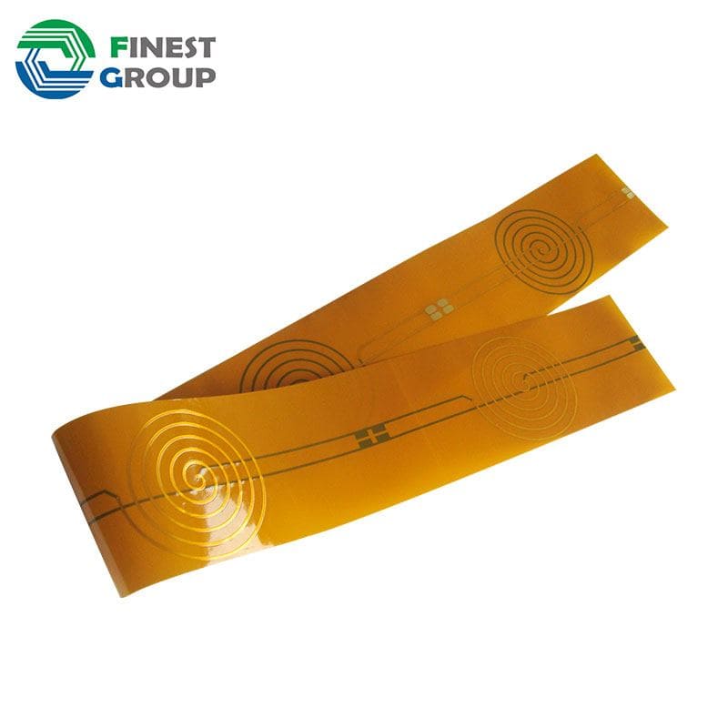
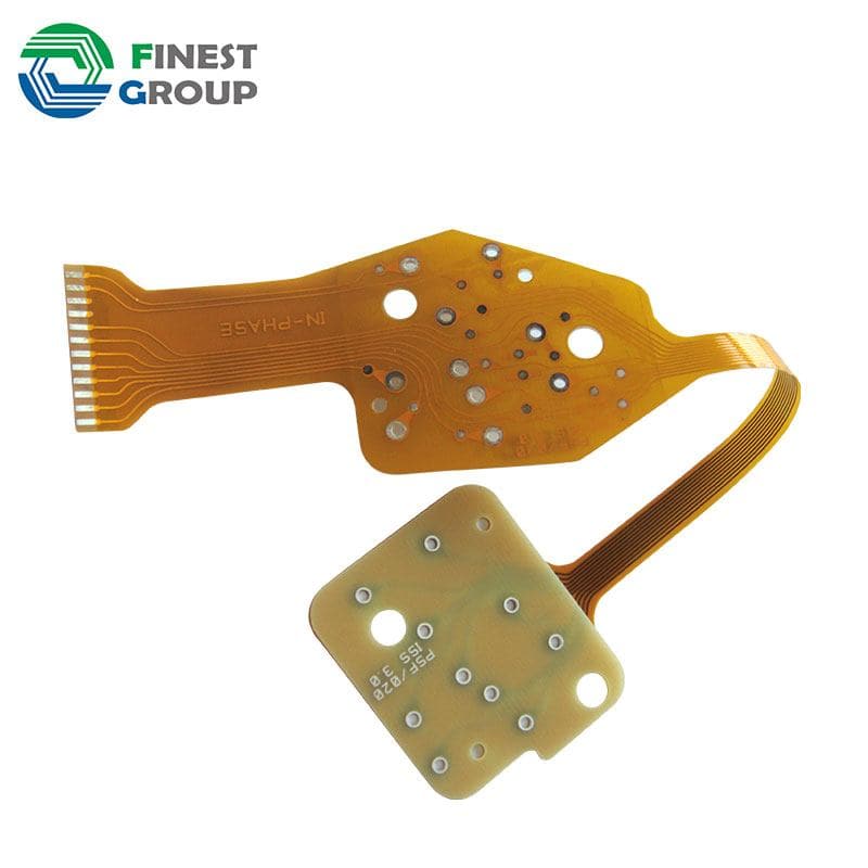
Flexible PCBs: Conquering Space Constraints
Imagine a PCB that can bend and twist without compromising functionality. This is the magic of flexible PCBs. These PCBs are constructed using a flexible polymer substrate instead of the rigid fiberglass traditionally used. This unique characteristic offers several advantages:
- Space-Saving Designs: Flexible PCBs can conform to complex shapes and fit into tight spaces where rigid PCBs would be impractical. This makes them ideal for applications like wearable electronics and compact medical devices.
- Improved Reliability in High-Vibration Environments: Their inherent flexibility allows them to absorb vibrations and shocks, enhancing reliability in applications prone to such conditions. This can be crucial in applications like aerospace and automotive electronics.
However, working with flexible PCBs requires specific considerations:
- Manufacturing Complexity: The fabrication process for flexible PCBs is generally more complex compared to rigid PCBs, potentially impacting the cost and lead time.
- Electrical Performance: While advancements are being made, flexible PCBs may exhibit slightly higher signal loss compared to rigid counterparts due to the nature of the materials used.
Applications: Flexible PCBs find their place in various innovative applications:
- Wearable electronics: Their flexibility and lightweight nature make them ideal for smartwatches, fitness trackers, and other wearable devices.
- Consumer electronics: Flexible PCBs are increasingly being used in smartphones and other compact devices to maximize space utilization.
- Medical devices: Their ability to conform to body contours makes them suitable for medical implants and other wearable medical devices.
While presenting unique design possibilities, flexible PCBs necessitate careful consideration of their fabrication complexities and potential electrical trade-offs.
The final frontier in our exploration of specialized PCB materials brings us to a solution that merges the rigidity of traditional PCBs with the flexibility of their counterparts:
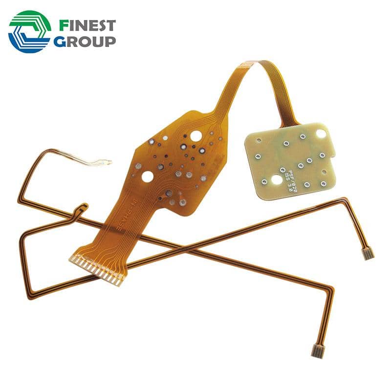
Rigid-Flex PCBs: Combining Rigidity and Flexibility
Rigid-flex PCBs offer the best of both worlds. These PCBs strategically combine rigid and flexible sections within a single board, allowing for:
- Space Optimization: Similar to flexible PCBs, rigid-flex designs enable efficient utilization of space by incorporating flexible sections that can fold or bend. This is crucial in applications with severe space constraints.
- Improved Signal Integrity: Rigid sections maintain the structural integrity needed for critical components and high-speed signal transmission. This ensures optimal electrical performance while offering the flexibility to navigate complex shapes.
Here are some applications that leverage the unique advantages of rigid-flex PCBs:
- Portable electronics: These PCBs are ideal for devices like smartphones and laptops, where space optimization and component density are crucial.
- Medical devices: Rigid-flex PCBs can be used in medical implants and other devices requiring a combination of flexibility for conformability and rigid sections for housing critical components.
- Robotic systems: The ability to maneuver around tight spaces and handle movement demands makes them suitable for robotic applications.
Table 6: Key Considerations for Rigid-Flex PCBs
| Factor | Description |
|---|---|
| Design Complexity | Designing and manufacturing rigid-flex PCBs requires specialized expertise due to the integration of rigid and flexible sections. |
| Higher Cost | The complex fabrication process typically translates to a higher cost compared to standard rigid or flexible PCBs. |
Key Properties to Consider When Selecting PCB Material
Choosing the right PCB material isn’t a one-size-fits-all proposition. Just like selecting the ideal ingredients for a recipe, it requires careful consideration of several factors to ensure your electronic device functions flawlessly. Here are three fundamental properties that play a pivotal role in your decision-making process:
Thermal Conductivity: Ensuring Efficient Heat Dissipation
Imagine a car engine – if it can’t efficiently expel heat, it risks overheating and potential breakdown. Similarly, electronic components generate heat during operation. The PCB material’s thermal conductivity determines how effectively it can dissipate this heat:
- Heat Transfer: Materials with high thermal conductivity, like aluminum or metal core PCBs, excel at transferring heat away from components and into the surrounding environment. This is crucial for high-power devices like power converters and LED drivers that generate significant heat. Studies have shown that aluminum PCBs can achieve thermal conductivities exceeding 200 W/mK, compared to FR4’s 0.3 – 0.4 W/mK.
- Preventing Overheating: Efficient heat dissipation safeguards electronic components from overheating. Excessive heat can damage components, shorten their lifespan, and even lead to device failure.
Therefore, for applications where heat generation is a concern, prioritizing materials with high thermal conductivity becomes essential.
Table 7: Thermal Conductivity of Common PCB Materials
| Material | Thermal Conductivity (W/mK) |
|---|---|
| FR4 | 0.3 – 0.4 |
| Aluminum | 200+ |
| Metal Core PCBs (varies) | > 100 |
drive_spreadsheetExport to Sheets
Remember: Thermal management is a critical aspect of PCB design. Selecting the right material with adequate thermal conductivity is the first step towards ensuring the reliability and longevity of your electronic device.
Beyond ensuring efficient heat dissipation, another crucial factor to consider is the material’s impact on signal transmission:
Dielectric Constant: Maintaining Signal Integrity
In the world of electronics, information travels as electrical signals along conductive paths on the PCB. The dielectric constant of the PCB material plays a vital role in this process:
- Signal Speed: The dielectric constant directly influences the speed at which signals travel through the PCB. Lower dielectric constants allow for faster signal propagation. This becomes increasingly important for high-frequency applications where even slight delays can disrupt signal integrity.
- Signal Loss: As signals travel through the PCB, they experience some degree of attenuation. Materials with lower dielectric constants exhibit lower signal loss, ensuring the signal strength remains within acceptable limits. This is crucial for maintaining data accuracy and preventing errors in high-speed data transmission.
Here’s an example: FR4, a commonly used material, has a dielectric constant of around 4.3. This translates to a good balance between affordability and functionality for many applications. However, for high-frequency applications exceeding 1 GHz, signal loss in FR4 can become significant. In such cases, specialized materials with even lower dielectric constants, like high-frequency laminates or ceramic substrates, become the preferred choice.
Table 8: Dielectric Constant of Common PCB Materials
| Material | Dielectric Constant |
|---|---|
| FR4 | 4.3 – 4.5 |
| CEM-3 | 4.2 – 4.5 |
| High-Frequency Laminates (varies) | 3.0 – 3.5 |
| Ceramic Substrates | 8.5 – 9.5 (Note: Lower values available) |
drive_spreadsheetExport to Sheets
Remember: Selecting a PCB material with an appropriate dielectric constant is vital for ensuring reliable signal transmission, especially in high-frequency applications. A lower dielectric constant translates to faster signal speeds and minimized signal loss, safeguarding data integrity and overall device functionality.
Key Properties to Consider When Selecting PCB Material (continued)
While technical specifications are crucial, the financial aspect also plays a significant role in bringing your project to life:
Cost-Effectiveness: Balancing Performance with Budget
Imagine building a house – you need a sturdy foundation, but you also want to stay within budget. Similarly, PCB material selection involves striking a balance between desired performance and cost:
- Material Costs: Different materials have varying price points. FR4, for instance, is a cost-effective option suitable for many applications. However, high-performance materials like metal core PCBs or ceramic substrates come at a premium due to the specialized materials and intricate manufacturing processes involved.
- Fabrication Costs: The complexity of the material can also influence fabrication costs. Simpler materials like FR4 typically have lower associated fabrication costs compared to their more advanced counterparts.
Finding the right balance often involves:
- Prioritizing Needs: Carefully assess the specific requirements of your project. If high thermal conductivity is paramount, a metal core PCB might be necessary, even though it comes at a higher cost. On the other hand, for a low-power application where cost is a major concern, FR4 might be a suitable choice.
- Exploring Alternatives: Research alternative materials that offer comparable performance at a potentially lower cost. For example, CEM-3 can be a cost-effective alternative to FR4 for low-power applications.
- Consult a Manufacturer: Partnering with an experienced PCB manufacturer allows you to leverage their expertise. They can guide you towards materials that meet your requirements while considering budget limitations.
Table 9: Cost Comparison of Common PCB Materials
| Material | Cost |
|---|---|
| FR4 | Low |
| CEM-3 | Lower than FR4 |
| Metal Core PCBs | High |
| High-Frequency Laminates | Moderate to High |
Remember: Striking the right balance between cost and performance is essential. While high-performance materials offer superior properties, they often come at a premium. Carefully evaluate your project requirements and explore cost-effective alternatives to achieve optimal results without exceeding your budget.
Additional Factors Influencing PCB Material Selection
Choosing the right PCB material goes beyond just the fundamental properties we’ve discussed. Several additional factors come into play, ensuring your PCB adheres to environmental regulations, meets safety standards, and functions flawlessly. Let’s delve into three such important considerations:
Lead-Free Solder Compatibility: Meeting Environmental Regulations
Environmental consciousness has become a driving force in the electronics industry. Lead, once a common component in solder, has been restricted due to its harmful ecological impact. This necessitates selecting PCB materials compatible with lead-free solders:
- Material Compatibility: Certain PCB materials, particularly those with high halogen content, can exhibit adverse reactions with lead-free solders. This can lead to weak solder joints and potential component failure.
- Environmental Regulations: Restriction of Hazardous Substances (RoHS) regulations restrict the use of lead and other hazardous materials in electronic devices. Choosing lead-free solder compatible materials ensures your PCB complies with these regulations.
Many PCB material manufacturers offer lead-free compatible options. Working with a reputable PCB assembly service provider can help you navigate these regulations and select materials that meet environmental standards.
Table 10: Lead-Free Solder Compatibility Considerations
| Factor | Description |
|---|---|
| Material Composition | Opt for materials with low halogen content for optimal compatibility with lead-free solders. |
| Manufacturing Expertise | Partner with a PCB assembly service provider experienced in working with lead-free compatible materials and adhering to RoHS |
Beyond environmental regulations, safety standards play a crucial role in ensuring the reliability and functionality of your electronic device:
RoHS Compliance: Aligning with Safety Standards
The Restriction of Hazardous Substances (RoHS) directive establishes limitations on the use of specific hazardous materials in electronic equipment. Selecting PCB materials that comply with RoHS safeguards against potential safety hazards:
- Material Restrictions: RoHS restricts the use of lead, mercury, cadmium, certain brominated flame retardants, and specific phthalates in electronic components. Compliant PCB materials adhere to these restrictions.
- Safety Assurance: Using RoHS compliant materials minimizes the risk of fires, toxic fumes, and other safety hazards associated with certain restricted substances. This is especially crucial for applications in safety-critical environments like medical devices or aerospace electronics.
Remember: Non-compliance with RoHS regulations can lead to product recalls and potential legal repercussions. Partnering with a reliable PCB supplier that prioritizes RoHS compliance ensures your devices meet the necessary safety standards.
Table 11: Understanding RoHS Compliance
| Factor | Description |
|---|---|
| Restricted Substances | Lead, mercury, cadmium, specific brominated flame retardants, and certain phthalates. |
| Benefits | Reduced risk of safety hazards, avoids potential legal issues. |
Enforcing RoHS compliance is not just about meeting regulations; it’s about prioritizing the safety of users and the environment. Choosing compliant PCB materials demonstrates your commitment to responsible manufacturing practices.
While we’ve covered essential properties and external regulations, achieving optimal PCB functionality requires attention to detail:
Impedance Control: Mitigating Signal Reflections
Imagine a highway – a smooth, uninterrupted road allows for efficient traffic flow. Similarly, controlled impedance in a PCB ensures smooth signal transmission:
- Signal Integrity: Impedance mismatch can cause signal reflections, distorting the signal and potentially leading to data errors or malfunctions. Precise control of the PCB material’s electrical properties like dielectric constant and trace width is crucial for maintaining consistent impedance.
- High-Speed Applications: In high-frequency applications, even minor impedance variations can significantly disrupt signal integrity. Specialized materials with predictable electrical characteristics are often necessary to achieve the required level of control.
Here are some methods to achieve impedance control:
- Material Selection: PCB materials with well-defined electrical properties are crucial for predictable impedance behavior.
- Trace Design: The width and thickness of the copper traces significantly influence impedance. PCB design software incorporates impedance calculators to ensure proper trace dimensions.
Table 12: Maintaining Impedance Control
| Factor | Description |
|---|---|
| Material Selection | Opt for materials with consistent electrical properties like dielectric constant. |
| Design Techniques | Utilize PCB design software with impedance calculators to determine optimal trace width and thickness. |
drive_spreadsheetExport to Sheets
By prioritizing impedance control, you safeguard against signal integrity issues and ensure your PCB functions flawlessly, especially in high-speed applications.
In conclusion: Selecting the right PCB material is a multifaceted decision. Understanding the interplay between thermal conductivity, dielectric constant, cost, and other crucial factors empowers you to make informed choices. Furthermore, adhering to environmental regulations and safety standards ensures responsible manufacturing practices. Remember, the ideal PCB material forms the foundation for a reliable and high-performing electronic device.