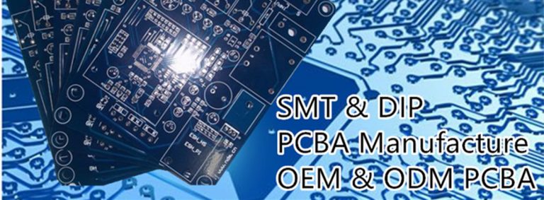

The Method of interconnection of PCB board
Many people in the PCB class know that, do you know what interconnection methods it has? Electronic components and electromechanical components have electrical contacts, and the electrical connection between two discrete contacts is called interconnection. The electronic devices must be interconnected in accordance with the schematic circuit diagram in order to realize the predetermined function. So what are the ways to interconnect the PCB board?
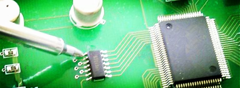
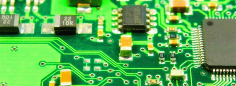
1. Welding method
The advantages of this connection method are simplicity, low cost, high reliability, and can avoid failures caused by poor contact; the disadvantage is that interchange and maintenance are not convenient enough. This method is generally suitable for components with fewer external leads.
PCB wire welding
This method does not require any connectors, as long as the external connection points on the PCB printed board are directly welded to the components or other parts outside the board with wires. For example, the horn and battery box in the radio.
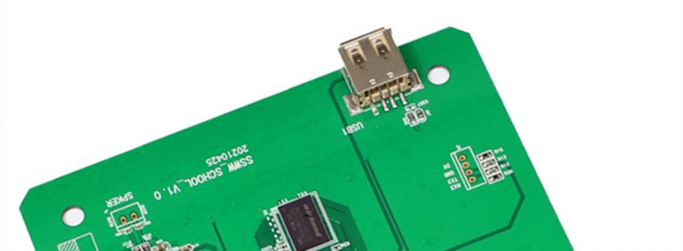
PCB cable welding
The two PCB-printed boards are connected by a flat cable, which is reliable and not prone to connection errors, and the relative position of the two PCB-printed boards is not restricted.
Direct welding between PCBs
The printed boards are directly welded. This method is often used for the connection of two printed boards at an angle of 90 degrees. After connection, it becomes a whole PCB printed board part.

2. Connector connection method
In more complicated instruments and equipment, connector connections are often used. This “building block” structure not only ensures the quality of mass production of products, reduces the cost of the system, but also provides convenience for debugging and maintenance. When the equipment fails, the maintenance personnel do not need to check the component level (that is, check the cause of the failure and trace the source to the specific component. This work takes a considerable amount of time), as long as it is judged which board is abnormal. It can be replaced immediately, so as to quickly troubleshoot, shorten downtime, and improve equipment utilization. The replaced circuit board can be repaired within ample time and used as a spare part after repair.
Printed board socket
In more complex instruments and equipment, this type of connection is often used. This method is to make a printed plug from the edge of the PCB printed board, and the plug part is designed according to the size of the socket, the number of contacts, the distance of the contacts, the position of the positioning hole, etc., to match the special PCB printed board socket.
Standard pin connection
This method can be used for external connection of printed boards, especially pin connections are often used in small instruments. When two printed boards are connected through standard pins, the two printed boards are generally parallel or perpendicular, which is easy to achieve mass production. The above is the interconnection method of the PCB board, I hope to help everyone.