How to Replace Printed Circuit Board SMD Components?
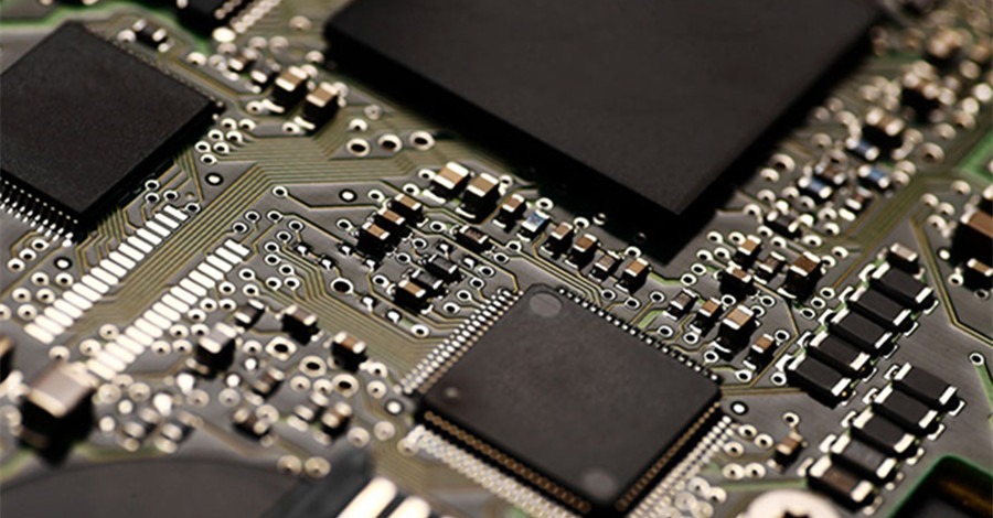
One thing that is very common in SMT chip processing is electronic components. So how to replace SMD components in the circuit board processing process?
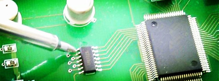
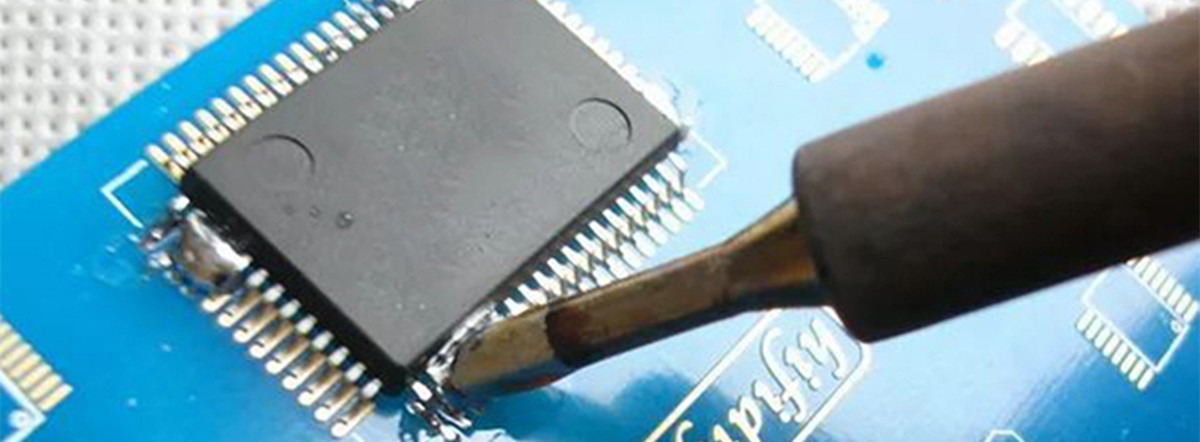
First, prepare a temperature-controlled electric soldering iron with a ground wire. The width of the soldering iron tip should be equal to the metal end surface of the chip PCBA assembly. The temperature of the soldering iron tip must reach 320°C. In addition, prepare a pair of tweezers for removing the tin. Use fine low-temperature rosin welding wire for welding, the welding steps are as follows:
1. Place the soldering iron tip directly on the upper surface of the damaged component. When the solder on both sides of the component and the adhesive underneath melt, use tweezers to remove the component.
2. Use a tin strip to remove the tin remaining on the circuit board. Then wipe off the adhesive and other stains on the original pad with alcohol.
3. Only heat an appropriate amount of solder on one side of the pad on the circuit board.
4. Use tweezers to place the new part on the pad. Quickly heat the new tin on the pad, let the molten tin contact the metal end of the thin-plate component, and then gently “stick” it. Do not touch the new components with the tip of the soldering iron.
5. One end of the newly replaced board has been fixed, and the other end can be welded.
Be sure not to solder too much. If the solder flows under the part, the pads will short-circuit. When soldering, the molten tin can only immerse into the metal end surface of the component, and the soldering iron tip cannot touch the component. In these two steps, the right amount of solder is the key to success.